Table Of Content
Camber is generally introduced to an airfoil to increase its maximum lift coefficient, which in turn decreases the stall speed of the aircraft. The camber line is a line drawn equidistant between the upper and lower surface at all points along the chord. Highly cambered airfoils produce more lift than lesser cambered airfoils, and an airfoil that has no camber is symmetrical upper and lower surface. A supercritical wing also uses a supercritical airfoil to reduce the strength of shock waves, thereby reducing wave drag. This principle is used in transonic wing and airfoil design to control the expansion of the flow to supersonic speed and its subsequent recompression.
The Advantages of Cambered Airfoils
For example, it is known that increasing the camber at the leading edge of an airfoil can increase its maximum lift coefficient to a point, but camber will also increase pitching moments. It has a point of maximum thickness fairly aft on the chord, with a relatively flat upper surface with a slight camber. The aerodynamic principle used in transonic wing and airfoil design is to control the expansion of the flow to supersonic speed and its subsequent recompression, making the leading edge pressure distribution less “peaky” and more uniform.
United Airlines and National Aviation Academy Launch Career Pathway Partnership
By definition, the lift force or lift force per unit length, , acts in a direction that is perpendicular to the free-stream velocity, . The corresponding drag or drag per unit span, , is in a direction parallel to . Notice, however, that in some cases, the axial or chord force may be defined as positive when pointing toward the leading edge, so it is essential to know the sign convention being used. Each airfoil produces a differing lift coefficient for a given angle of attack.
Landing and 1G Stall
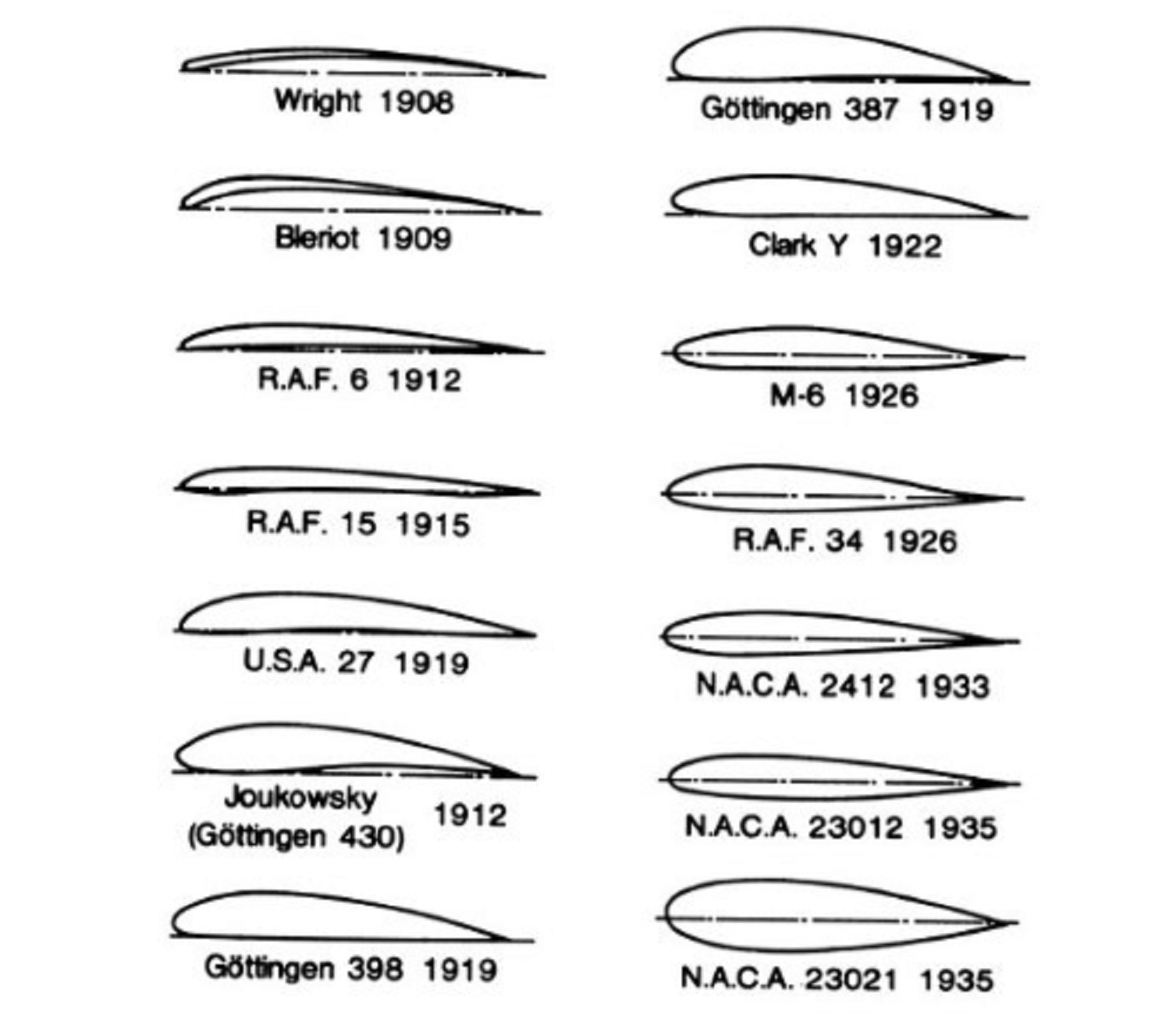
Airfoils are designed to function at their best at a specific “design CL.” When choosing an airfoil for an airplane, the design CL is the cruise value. Compare the drag coefficient of candidate airfoils when they are at this design lift coefficient to find the one that has the lowest drag at the actual cruise condition of the airplane you are designing. With over a century of airfoil shape designs created, there is a wealth of research and actual flight performance information available that can be leveraged when designing airfoil shapes.
Induced Drag:
Applying Bernoulli’s Principle of Pressure, when an airfoil is moving, the airfoil’s shape causes an increase in velocity of air across the upper surface of an airfoil. This results in a drop in pressure in the area above the airfoil and an increase in pressure below the airfoil. The pressure difference between the upper and lower surface creates lift force. The vast majority of other airfoil design programs which claim to perform inverse design are based on trail-and-error re-drawing of the airfoil. True inverse design is vastly different and has previously been reserved for aerodynamic experts. AeroFoil puts the inverse design process within reach of anyone with a general knowledge of how a wing works.
How Does Aerodynamic Lift Occur?
You may now be wondering how engineers go about designing or specifying an airfoil. NASA/NACA, among others, has completed a LOT of work designing, parameterizing and creating a library of airfoil sections that are often used (or used as a starting point) when designing a new aircraft. Thankfully, there are a number of references on the internet where you can go and download the coordinate geometry for just about any airfoil you may want to view or use.
Center of Pressure
MIT and NASA engineers demonstrate a new kind of airplane wing - MIT News
MIT and NASA engineers demonstrate a new kind of airplane wing.
Posted: Sun, 31 Mar 2019 07:00:00 GMT [source]
Of course, the numerical cost (and time) to obtain a solution increases commensurately with the number of grid points. Notice also that as an artifact of this construction, the leading edge of the airfoil shape protrudes very slightly forward of the -axis, but this effect is of no practical significance. For a symmetric airfoil, the center of this nose circle lies on the -axis. For all cases, the nose circle is drawn and geometrically blended into the upper and lower surface coordinates; some care should be taken in conducting this process numerically. The NACA 0012 is a symmetric airfoil, so at zero angle of attack (or almost at 0.1 degrees in the case), the upper surface pressure distribution is identical to the lower surface.
Thin Airfoil Models of Aerodynamics
Today, supersonic aircraft with multiple airfoils, which is common for helicopters and UAVs, traverse the airways. Designing airfoil shapes for these aircraft requires a good understanding of how airfoil shape impacts lift. Now consider expanding Wiessinger’s approximation into many elements that represent the airfoil camberline in detail. This approach is referred to as numerical thin-airfoil theory (and is the discretized representation of formal thin-airfoil theory). There the extension of Weissinger’s approximation should be seen, that is, we basically break the camber line into individual segments () indicated by the purple sections.
Symmetrical Airfoils and Their Applications
Theslower eddies close to the surface mix with the faster moving masses of air above. As aresult, the air molecules next to the wing surface in a turbulent boundary layer movefaster than in a laminar boundary layer (for the same flowcharacteristics). Thus due to the curved, cambered surface of the wing, there exists a pressure gradientabove the wing, where the pressure is lower right above the surface. Assuming a flatbottom, the pressure below the wing will be close to the ambient pressure, and will thuspush upwards, creating the lift needed by the airplane.
This is understandable, as the initial problem was simply to get the aircraft off the ground. However, the problem of mastering sustained flight over long distances, which requires balancing the airplane aerodynamic forces of thrust, drag, lift, and gravity, was quickly added to the analysis. This resulted in dramatically different airfoil shapes--many by the National Advisory Committee for Aeronautics (NACA). The regionwhere fluid must flow from low to high pressure (adverse pressure gradient) is responsiblefor flow separation. If the pressure gradient is too high, the pressure forces overcomethe fluid's inertial forces, and the flow departs from the wing contour.
In reality, the selection of an airfoil is an iterative process that accompanies a detailed performance estimate of the aircraft. It’s important to note when looking at the graphs below that the actual aircraft efficiency ratio will be much lower than what is shown here. These plots are only looking at the 2D airfoil characteristics and do not include sources of drag such as the 3D wing, fuselage, tailplane etc.
Getting more into the technical and mathematical side of airfoil design, here are two popular names that you may see when researching airfoil shapes. Reading up about them might be a good way to learn about the nuances of how designers create airfoils. The wing for many types of aircraft is sized by stall speed, which we will discuss in the next section.
Naturally, the importance of testing techniques here must be noticed, and airfoil measurements must be made carefully using established methods. Nevertheless, most of the understanding of airfoil section characteristics, including the effects of geometric shape, has come from measurements. Supersonic airfoils generally have thinner sections constructed of angled planes called double-wedge airfoils or opposed circular arcs called biconvex airfoils, as shown in the figure below.
A beautiful wing design solution inspired by owl feathers - Phys.org
A beautiful wing design solution inspired by owl feathers.
Posted: Wed, 27 Sep 2017 07:00:00 GMT [source]
Thus, a pressuregradient is created, where the higher pressures further along from the radius of curvaturepush inwards towards the center of curvature where the pressure is lower, thus providingthe accelerating force on the fluid particle. Similarly, as thefluid particle follows the cambered upper surface of the wing, there must be a forceacting on that little particle to allow the particle to make that turn. As the list above indicates, accurate data and information are important keys for optimizing your airfoil design. These include knowledge of the aircraft and its materials, as well as accurate environmental data--to the degree possible--for where and how it will be utilized. To perform the actual calculations and analysis, it is highly recommended that designers use an advanced tool such as the one shown below. For practical reasons, all NACA airfoils have a finite thickness at their trailing edges, so the values of at are non-zero.
For example, the lift coefficient produced by a supersonic airfoil at a given angle of attack is the same for a flat plate, a diamond-wedge airfoil, or a biconvex airfoil. The drag, however, is different because the dominant source of drag in supersonic flight is wave drag, which depends strongly on the airfoil shape. These data are shown in the figure below in the form of lift coefficient, , versus angle of attack, , the pitching moment coefficient about the 1/4-chord versus , and the center of pressure location versus . The slope of the lift curve (i.e., the lift-curve slope, , and the slope of the moment curve, i.e., . By , the boundary layer has separated downstream of the shock on the upper surface, a phenomenon known as shock wave-induced flow separation, usually called shock-induced separation.
The favorable pressure gradients tend to give the airfoils lower drag than other airfoils, at least over a limited range of attack angles. Unfortunately, surface contaminants or other transition-causing disturbances quickly spoil the characteristics of laminar flow types of airfoils, sometimes resulting in significant adverse characteristics. As shown in the following figure below, the critical length dimension of an airfoil profile is defined in terms of its chordline; the chord is defined as the distance measured from the leading edge of the airfoil profile to its trailing edge. Some of the earliest known airfoil sections considered for aircraft concepts were patented in the 1880s by Horatio Phillips, as shown in the figure below, which were inspired by the wings of birds. Taking inspiration from nature is nothing new in engineering, but history shows that it should not necessarily be a basis for our engineering. Notice the thin, highly cambered profile shapes, which are now known to have poor aerodynamic efficiency compared to modern airfoils, at least under the operating conditions of most flight vehicles.


No comments:
Post a Comment