Table Of Content

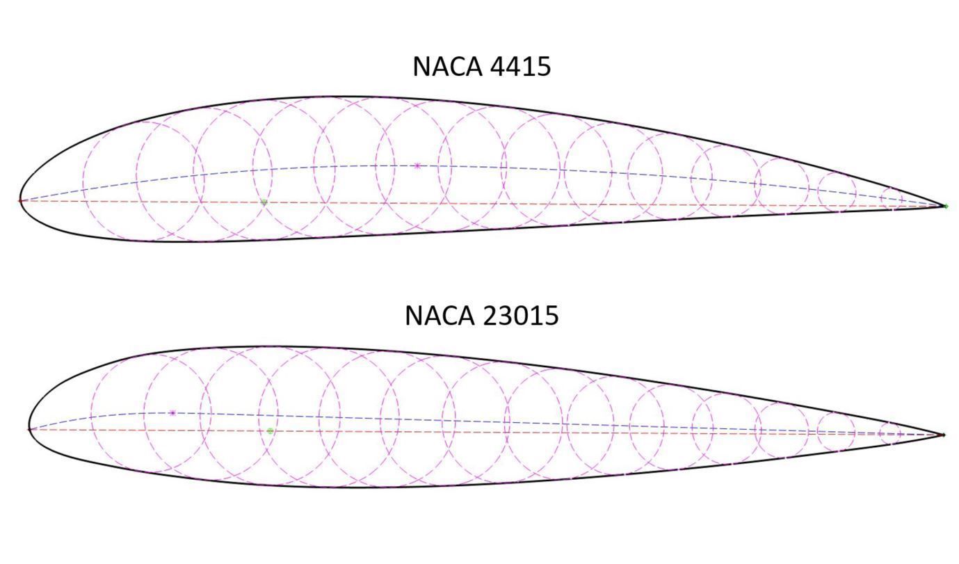
Simple in concept and critical (despite ad-hoc) component to aerodynamics. At its core, the Kutta condition implies either a smooth flow at the trailing edge of an airfoil or a stagnation point at the trailing edge. Conventional wisdom has in the past implied that the Kutta condition is a “viscous patch” that ties potential flow to a physical condition. Cambered airfoils, a few of which are shown below, often have rounded leading edges and thin tapered trailing edges. There are thousands of airfoils in current use, most selected or otherwise adapted to optimize their performance for their specific flight vehicle application. A common question is what airfoil section(s) is (are) used on particular aircraft.
How Does Aerodynamic Lift Occur?
Using the most suitable airfoil section or sections is fundamental to the success of the design of a wing, subsonic, transonic, or supersonic, or for other applications such as rotary-wing concepts and UAVs. To this end, many different types of airfoil sections have been geometrically tailored to give the best aerodynamic performance in the conditions of flight. For example, thicker and more cambered airfoils with rounded nose shapes are more suitable for slower flight speeds and low Mach numbers. In contrast, very thin airfoils with sharp leading edges are more suitable for high speeds and supersonic Mach numbers.
Airfoil Forces and Moments
For example, in a design problem, it may be necessary to select an airfoil shape to meet a set of aerodynamic requirements. Quantities such as maximum lift coefficient, minimum drag coefficient, maximum lift-to-drag ratio, etc., can all be necessary for quantifying the aerodynamic characteristics of airfoils and can also be a basis for airfoil selection. In some cases, the characteristics of candidate airfoils may need to be compared, which should always be done on a non-dimensional basis in terms of force coefficients, such as in the form of a polar. Historically, the design of airfoil shapes for specific applications has advanced through an evolutionary process, synergistically combining theoretical analysis, wind tunnel experiments, and flight testing. Engineers often begin by selecting candidate airfoil shapes with the desired characteristics and then employing mathematical models and CFD simulations to predict aerodynamic performance.
Nose Radius
From Paper Planes To 3D-printed Aircraft - Mirage News
From Paper Planes To 3D-printed Aircraft.
Posted: Fri, 12 Apr 2024 07:00:00 GMT [source]
Higher-wing-loading airplanes, or airplanes with extremely short takeoff distance requirements, may take off with some flap deflection to reduce liftoff speed and takeoff roll. For these airplanes, the wing design and airfoil choice should be evaluated with the flaps in the nominal takeoff position. The third flight condition/configuration we need to check is takeoff and initial climb. This rarely sizes the wing, but we do need to be mindful of both maximum lift and drag of the wing in takeoff configuration. Not surprisingly, airfoil shapes can vary greatly depending upon the type of aircraft, flight environment, air speed, and other factors, as shown in the table below. Starting at thesurface of the wing and moving up and away from the surface, the pressure increases withincreasing distance until the pressure reaches the ambient pressure.
Airfoils, Where the Turbine Meets the Wind - Energy.gov
Airfoils, Where the Turbine Meets the Wind.
Posted: Wed, 10 May 2023 07:00:00 GMT [source]
Periodically, a new airfoil or family of airfoils appear that are widely publicized as “advanced” or “new high-performance” airfoils. Designers and builders will be very tempted to adopt this new technology to improve their airplanes. Riblett was a man with many hobbies, and since finishing his book, he’s restored a number of old cars, including a 1929 Model A Ford Huckster Wagon, and built a railroad pump car from 1890 drawings. Ever the problem solver, he replaced the gear drive with a chain and used modern ball bearings to make it easier to pump. In his garage was an unnamed airplane he designed decades ago, a single-seat, tube-and-rag, high-wing pusher with folding wings and tricycle gear.
Bearhawk 4-Place Aircraft Available With DeltaHawk Engine
For most airfoils with positive camber, the value of is negative, so the center of pressure is generally behind the 1/4-chord. In particular, notice that the center of pressure will be a function of the lift coefficient (and hence also the angle of attack), so it is not a fixed point, as shown in the above figure. Because the center of pressure is a moving point and may not even be on the airfoil’s chord, the center of pressure is only sometimes a convenient concept to use in aerodynamics. Hence, the center of pressure to resolve the forces and moments is used sparingly in practice, even though the pitching moment here is zero, by definition.

It is also possible to mimic an infinite span and aspect ratio in the wind tunnel. One approach is to span the wing from wall to wall, thereby eliminating the tip vortices. Another common practice is to test a short-span wing between two “false” walls, as shown in the photograph below. Post-stall, the flow always tends to become inherently more three-dimensional on any lifting surface, regardless of how it is being tested. It can be deduced from the figure above that the shear stresses, in the aggregate, will act in a direction primarily parallel to the chord line, so it will contribute significantly to the drag force on the airfoil section.
Often the new airfoil was designed for airplanes with a far different wing loading, cruise speed or cruise altitude than the new airplane a designer is working on. The new airfoil may actually perform worse at the actual flight conditions for the airplane than another choice. Once the size and planform of the wing have been determined, it’s time to choose (or design) the airfoil. The airfoil must provide the right aerodynamic characteristics to give the airplane its best performance and acceptable flight characteristics. The most important thing to understand about selecting an airfoil is that the airfoil must be evaluated at the actual flight conditions that are important for this particular airplane. Note the distinct difference between our panel code and the model depicted in the first Figure.
Notwithstanding, the tool provides a great insight into the choice of airfoil made by each aircraft manufacturer. If you are looking for a more in depth mathematical model to estimate the total drag of an aircraft you can read Part 9 of this series. Dynamic pressure is defined as the kinetic energy per unit volume of a fluid particle and is a function of air density and velocity.
This phenomenon is exaggerated even further by the installation of fixed flaps and a slat on the CH-750 which further increases the lift coefficient of the airfoil with a corresponding large drag penalty (not shown here). AeroFoil is an airfoil design and analysis program written in Visual Basic. AeroFoil uses the vortex panel method and integral boundary layer equations to calculate drag, lift, and airfoil pitching moment at different angles of attack. The pressure differential--low pressure above and higher pressure below--creates lift for the aircraft. Along with better stall avoidance characteristics, the primary advantage of cambered airfoils is the wide range of possible design geometries that allow for optimization of lift to drag--or coefficient of lift to coefficient of drag--ratios.
Weissinger’s approximation is much more physically intuitive than the formal thin airfoil theory, so please focus to understand and master this first. The result of this model is a very flexible and is rather simple model of airfoil lift aerodynamics. The model is also extendable to the aerodynamics of a cambered airfoil, flapped airfoils, and airfoils operating together. Designing an airfoil that maximizes the performance of the aircraft should always be the objective.
In that case, these values reveal much about the aerodynamic operating state of the airfoil, and the coefficients also allow comparisons of the effects of wings of different shapes and sizes. For this reason, airfoil data (measured or computed) are generally presented in terms of non-dimensional coefficients. The origin of the net aerodynamic forces on an airfoil or wing, such as lift and drag, comes from the integrated effects of the pressure and the boundary layer shear stress distributions acting over its surface, shown in the figure below.


No comments:
Post a Comment